Homemade programmer for bios firmware. We restore on the programmer after an unsuccessful update. If you still need to reflash
Any modern digital technology, both computer and household, works according to a specially written action algorithm. This algorithm, in the form of program code, is recorded in a special program, otherwise called device firmware. Sometimes, for example, in the case when the equipment was turned on without a surge protector in a thunderstorm, this firmware flies.
Sometimes a function can be very long, and you may not need to run the first lines of code for debugging; this can be useful if you know the line number from which we want to start the next option. He can block it only when he reaches this line, avoiding the tedious and repetitive keystrokes.
Two more versions of this command are available that address our specific needs. The last, but not trivial or useless, change to this command is as follows. This allows us to debug in the best way: when this event occurs, which allows us to further facilitate our work.
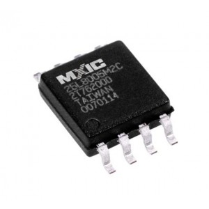
Dual BIOS SO-8
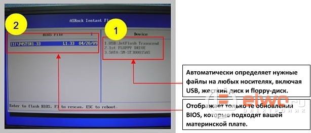
The program code that was recorded in the flash memory of the microcircuit starts to malfunction, and the device can no longer function normally. What to do in this case? Read the site instructions and find out. And here we need to find the firmware, in other words, the very program in the format necessary for flashing, clear the memory of the microcircuit, and then overwrite new program. In order to fill the firmware into the memory of the microcircuit, we need a programmer. Sometimes, if the device was released with “raw” firmware, flashing to a more recent one will allow you to add new functions to the device, or get rid of unpleasant bugs that poisoned your life when using this technique. I will give a simple example: on motherboards, the manufacturer provided for the possibility of updating the firmware by simply reading it from a USB flash drive, going into the BIOS and selecting.
Prepare the system and boot disk
If you are a Cossack, you can simplify some of the steps and procedures. Do not forget: this is a machine gun! You need to know the manufacturer, the type of motherboard and often its “revision”. You can find information directly from the motherboard. You can skip this point if you have standard and more modern equipment. If your board does not correctly recognize the disk size, write down the number of heads, sectors, and cylinders. Use a good floppy disk - of course you do not want the operation to fail due to bad sectors.
Then beginners will have a reasonable question, why do we need any programmers at all, if everything is solved so easily and simply in the BIOS? The fact is that this is possible only when we can go into the BIOS and select the desired option, or in other words, when the motherboard is at least somehow functioning. In case of problems with the BIOS, the motherboard can supposedly start when you press the power button on the PC, but there is no image telling us that the motherboard self-test was successful, either. How to be here? The firmware flew with us in this case, or something else?
On the floppy disk, move all the necessary files. The individual switches have the following meanings. If you have notes on the initial setup, exit it. A program that is immediately processed by the processor when you start your computer and which takes care of the correct hardware settings. It should set the chipset, memory time, bus speed, multipliers, voltage, etc. Well, because this is a program, it obviously contains some errors. These errors can be caused by computer instability or incompatibility between different devices.
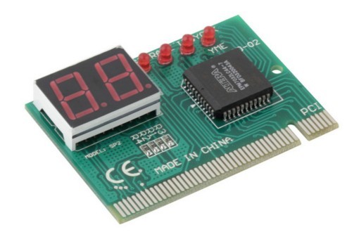
Post card
Here you first need to digress, and talk about what a POST card is, and why it is needed here. This is a special board for the PCI connector, which is stuck in it, and has an indication of POST codes, or in other words, an indication in the form of an alphanumeric code, ongoing software processes, the inclusion of the motherboard, on two seven-segment indicators. These POST codes, of course, each have their own decryption, by which we determine, in the event of a breakdown, at which stage, we have a failure. And if we see that testing on some of the POST codes hangs, we can with a certain degree of probability assume that the flown BIOS is guilty of a malfunction. Of course, before flashing, you must first perform all standard procedures in case of poor contact in the memory or processor sockets.
This will provide better stability, compatibility, and even better performance. Sometimes the situation can be much worse. Most motherboards are manufactured by Taiwanese companies. First of all, you should know what your motherboard is.
Some manufacturers also cannot post a warning on their website. The version of the motherboard is written directly on the board. A worse situation arises if you have a motherboard of an unknown manufacturer. In the past, there were a huge number of manufacturers who did not want to name their products. On these boards there is usually nothing, at best, only some product names that can be traced back to something. It is simply a fact that the lower purchase price of the board is bought back, among other things, due to the lack of support.
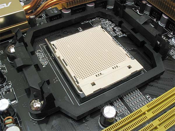
Processor socket
Insert the processor into the socket, raise and lower the lever 20 times, while the oxides, if they were on the connector pins, will be erased. Walk with a soft white eraser, on the contacts of RAM, on both sides, for the same purpose. Take a toothbrush, and spend 5 times, on each of the memory slots, along the connector along it. As practice shows, sometimes this is enough for the computer to work.
Whether recording a file with a high risk that it is not for your recording is up to you. You may experience the following issues. Flashing error - this can happen if the flash does not fire, for example, by pressing the reset button, the computer is delayed or an incorrect flashing program is used. In this case, there may be a certain probability of recovery through the boot block, but this depends on the phase in which the error occurred, and whether it is in order. The first is the main, the second is the backup.
In general, the general principles for minimizing this risk apply. The word "autonomous" is important. Nothing in the world explains. It is probably best to use a microfuel or tap. Hot or infrared soldering station. The actual flashing process already depends on the particular programmer or software.
By the way, if you changed the battery on the motherboard, do not forget to clear the CMOS by closing for 10 seconds, 2 pins Clear CMOS, on the motherboard with a jumper.
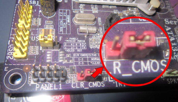
How to reset CMOS
If the motherboard was an Asrock model, such as the widespread N68 or G31 series, and the like, then you will need to remove the RAM modules and reinsert it, after replacing the battery, read about shadow RAM, who cares why this is done.
This completes the repair, and after connecting all the necessary components, the laptop should be fully operational. A technical guide to recording data on these memories is standard equipment in our technical department. In most cases, a wound will not cause damage, and there is no sign of injury. However, we do not blame the injury! This is a more difficult task that we cannot guarantee for success. In an exceptional case, even if the base plate is damaged, it can even damage the system board.
If you still need to reflash
So back to our rams). You have done all these procedures, but the motherboard as before does not want to work properly, and you decide to flash the BIOS. Here you need to know about what types of microcircuits and in which cases you can meet on motherboards. The types of memory chips that were found on obsolete motherboards, from the time of the Pentium 4, in the PLCC32 package, we will not particularly consider. They need a different type of programmer, much more difficult to manufacture, and expensive in cost if you buy ready-made.
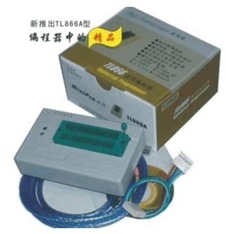
Programmer TL 866A
If someone really needs to flash such a memory chip, you need the TL 866A programmer, which can be ordered with Ali Express, this is only the programmer itself, without adapters and adapters, and it will cost about 2.5 thousand rubles. A complete set will naturally be more expensive. But as it turned out, there is an even cheaper solution to this problem, although less universal. This is the NANO USB Programmer, with E-bay, on Ali Express, for some reason I did not find it.
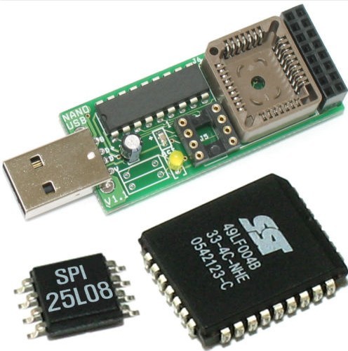
NANO USB Programmer
The decision to purchase it, due to its lesser versatility compared to the TL866A, is probably very controversial, but it also costs about half the price, about a thousand rubles. We are now interested in memory chips with SPI interfacefor which much cheaper and simpler programmers are required.
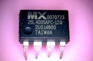
Ddip-8 BIOS Chip
The fact is that since about 2007, on motherboards of AMD and Intel platforms, a gradual transition has begun from BIOS chips, in the PLCC32 package, to chips with an SPI interface that have 8 legs, and are available in Dip-8 and So- 8.
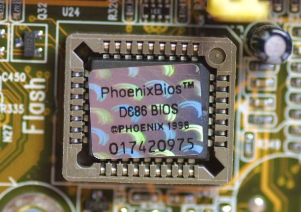
BIOS PLCC
The latter, as you already think, are released in the SMD version. So, these very microcircuits, on modern motherboards, are very often produced in the Dip-8 package, and are installed in a special socket.
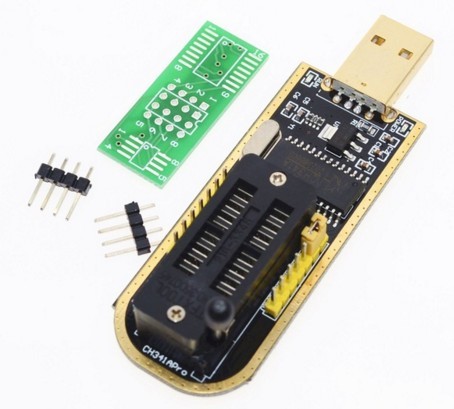
Programmer CH 341A
In this case, we can only remove the microcircuit from the socket, install it in the ZIF adapter of the programmer, flash it, and then install it back into the motherboard. By the way, before you erase the microchip and flash it with new firmware, be sure to save the current firmware on your hard drive. This will allow you to fill it back without any problems, in case the new firmware will not work stably, or in general will not be suitable for this device.
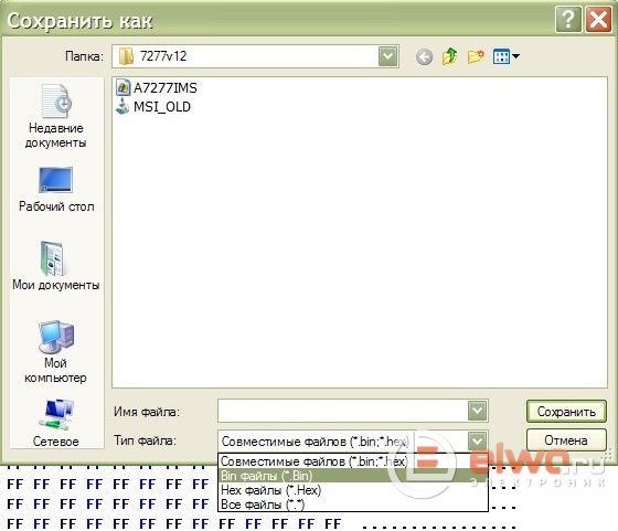
But where to get the firmware for the programmer, because it should be in the * format. binor *. hex, these are the formats of the firmware that the programmer understands, and on the official website of the manufacturer to update the firmware via a USB flash drive, you can download only some generally incomprehensible left format. As practice has shown, this is most often the same binary format *. bin, only with a different extension, and to flash it we just need to change the file extension to * .bin. How everything turns out to be simple) ...
But it wasn’t there, they rejoiced early) ... For example, manufacturers of open source firmware do not upload monitors and other equipment, and access to them is available only in service centers, or you can ask someone to remove the dump from the working monitor. But fortunately the world is not without good people, and these firmwares, if you look very well, can still be found on specialized sites for repairing equipment. What to do if bIOS chip in our SO-8 package? Is it necessary to solder it before flashing? No by at least not always ... The Chinese industry produces a special adapter, a clip, which is attached to the top of the contacts of the microcircuit, we can flash it without soldering. But make a reservation, this option does not always work.
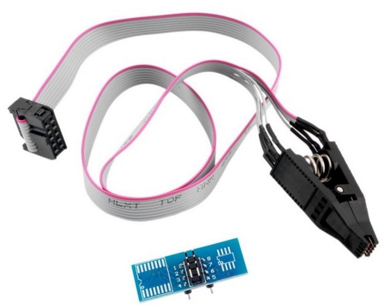
In this case, you will need to unsolder the memory microcircuit, and flash it by soldering to the adapter platform, or use the clip by holding the microcircuit into it, or such adapters having different widths of the installed microcircuit, 150 and 200 mil.
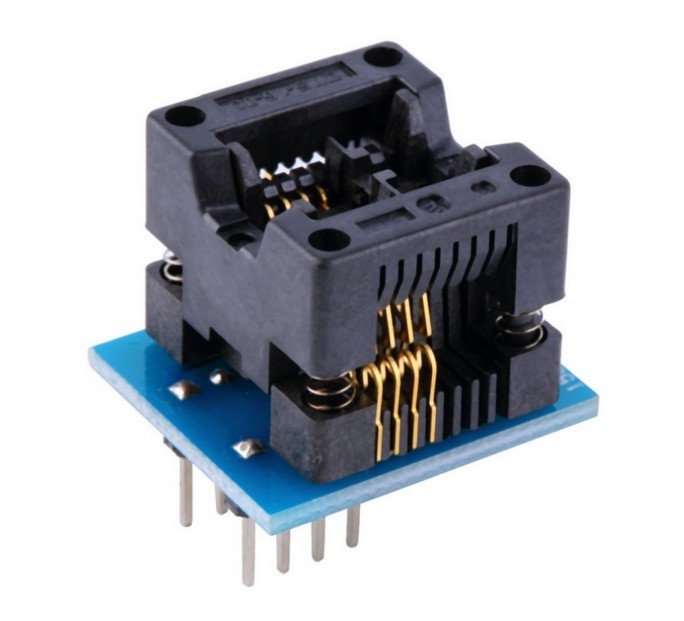
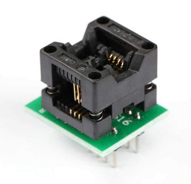
Adapters 200 and 150 Mils
How can I solder an SO-8 chip without a soldering iron? You can use Rose or Wood alloys, in extreme cases, you can take a lower temperature than solder for lead-free soldering, POS-61, apply it to the contacts of the chip, take a medical needle from the stainless steel, and pry it under one of the contacts of the chip, warming the soldering iron tip lift it up.
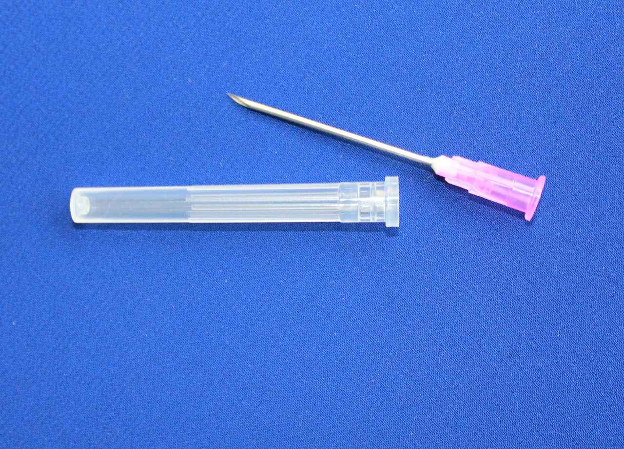
Then this procedure must be done in turn with all contacts. Then you need to remove the old solder from the contact pads on the board, applying flux, using a dismantling braid. I beat off my programmer and clip a long time ago by flashing the BIOS on just one motherboard. And now he often helps me when there are doubts about what the problem is, in the BIOS or not. If for some reason it is not possible to purchase an SPI programmer, you can solder a simple circuit yourself, for flashing chips in the Dip-8 package, most likely for one-time work, it will be enough for you.
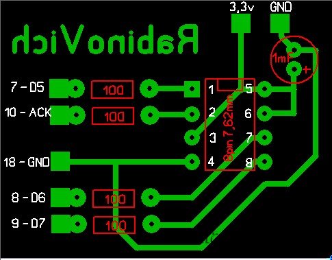
Electric scheme
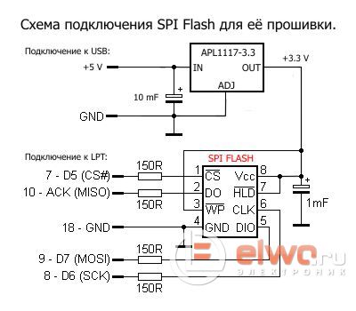
The stabilizer is 3.3 volts, in this case, if there is an urgent need, you can replace the tablet with a lithium battery, 2016-2032, it, fresh of course, produces about 3 volts, and such power will be enough for one-time firmware.
Instead of output
This conditionally - soft repair of motherboards is one of the simplest types of repair, and does not require any experience in soldering, or the presence of a soldering hair dryer, and other expensive tools and devices. I recommend the SPI programmer with Ali Express, and a clip for it, as an inexpensive solution, for flashing Motherboard BIOS boards, to all novice masters who still can not afford to purchase, for various reasons, the TL866A programmer. All successful repairs, AKV was with you.
1. Software recovery of the motherboard itself.
Modern motherboard models (Gigabyte has last 3 years on mainstream and top ones for sure), 2 microcircuits are immediately soldered on the board, in case of unsuccessful update it will boot from the backup mikruhi, and later fill the copy with the damaged one. Some models do not have the ability to repair the damaged one, and in the event of the death of the first, the second simply starts working for its place, respectively, after the death of the second mother will not start
There is still the possibility of recovery from bootblock, but it works if it doesn’t die completely and the bootlock is still alive and trying to start the system it detects a crooked BIOS amount. In this case, it tries to read from the HDD, or flopp. Some boards (Gigabats have this feature ) write a double to the HDD, which is the first to be connected to them, so you can connect this drive to restore it. To recover from a flopp, just write the firmware with the correct name to the floppy disk, it will be detected and restored. ) from the connected floppod, if the flop shows signs of life, then we easily got off
2. Hot swap recovery go hotswap. It works only on mothers, where it is not soldered, but sits in a socket and it can be picked up. Those. you need to find another working board with a similar one, i.e. so that the bed is the same and preferably the chips were from a common or from one of the similar families, then the procedure will definitely work. Convenience is made in advance on the board with the living for pulling the chip out of bed - threads, insulated wire, etc. if there are no special forceps, the board turns on, go to DOS (or the board's proprietary utility) to update, tear it out, insert the dead one and sew it up, if warnings about mismatching checksums appear, then they are ignored, because there is nothing to be afraid of - the native lies separately. Then the system turns off, we return our chip to each board and check the performance. This method will probably not work if the microcircuits are soldered into the boards, a hot swap does not work, of course you can take a chance and unsolder on a working board - but this is very risky - you can stay with 2 completely dead boards, and the dead one will already be electronics, not software part
3. Recovery on the programmer. This method is universal, i.e. You can flash any chip in any type of housing. If mikruha is soldered to the board, then remove it and solder it on the programmer board or use special panels. Of course, a limited number of microcircuits can be flashed on one programmer, but this usually applies to simple programmers, more “adults” are really universal, but they cost no more than 5 kopecks and are purchased mainly for stream repair, rather than home use to restore a couple of boards. Nevertheless, this method is universal, it completely replaces and expands the first 2 methods, and when they do not work, this is the only way out. The hot swap method is even an artificial method that was discovered empirically due to the unification by manufacturers of circuit board elements. I want to talk about one of the simple "home" programmers.
Essence of the process
The AsRock N68-PV-GS board came into my hands the other day, its previous owner gave it to me just like that. It has long been unsuccessfully stitched and has been trite replaced by another. But I’m not used to throwing out equipment that can be repaired by altering one chip and set about revitalizing the board - it will not be superfluous in the household, the platform is still not so ancient, socket AM2
The board does not need to be mirrored, it is already "correctly" drawn. When I do the wiring, I will present the textolite as if transparent - it’s much easier, at least to me
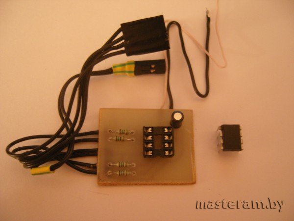
Essential Ingredients:
- Resistors 150 ohms 0.125W x 4pcs
- Capacitor capacitor 1mF 16-63v x 1pc
- 8pin socket 7.62mm x 1pc or special clamping panels for SMD chips, generally depending on the patient
- A few wires, I used wires of about 24AWG 12cm long
- Breadboard or textolite and all necessary accessories for etching and tinning
- Pin connectors x 5pcs
On the wiring (as in the diagram), the outputs to the LPT connector (DB25) are indicated by numbers, i.e. 7, 8, 9, 10 and 18. We need the first 4 contacts to transfer data, the 18th - earth. But you can use any 18 for a place in the range of 18-25. I specifically did not place the DB25 connector itself on the board, because not everyone will do it. Reasons for this 2:
1. Few contacts, only 5pcs, in order to spend 20p on this connector and put it on such a tiny board. It’s much easier to get these 5 pins and plug them into the connector itself
2. On modern boards, they no longer have a full LPT connector, manufacturers output pins on the board, to which you can connect an external / internal adapter and thereby get a DM25-F, i.e. LPT Thus, having made a full-fledged programmer on board with DB25-M, we will have to make the appropriate connector for the board or buy an adapter separately, as the board manufacturers advise. Of course, I have such an adapter ↓↓↓, I did not buy it, I made it myself from a floppy cable and a DB25-F connector removed from the old cable from the printer. But nevertheless, I did not make this connector on the programmer simply because I did not have it at hand and for reasons 1
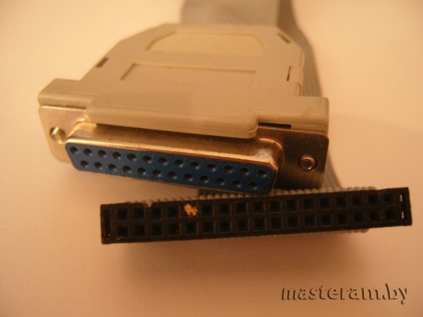
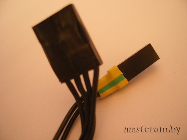
Homemade LPT adapter for modern motherboards. The flopp IDE connector fits perfectly on the pinouts of the boards, inserted a piece of toothpick as a limiter, so as not to miss
I made it easier, brought 5 contacts (I have 6 on the photo because 2 lands) for the pins of the board with the corresponding connectors, checked the board’s list (in fact, all the boards are the same, maybe only the "key" is the empty pin is in another place , and in the marking manual go in a different order) and set them to the right places, the programmer just uses the contact range of the 7-10 connector. I stuck the earth at 23 and 24 conclusions, because 18-25 earth
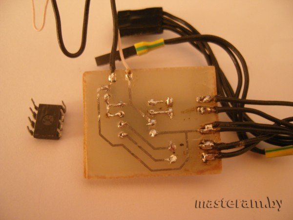
As a result, we should get about the following device:
To power the programmer, you need constant power 3.3v, as well as external mass. For this purpose I use an external full-fledged Gembird 400W PSU. I have it like a laboratory PSU, I would not trust him with a live configuration because of its quality) I got it from one good person - this PSU apparently does not have enough real power and it was not enough for the previous owner, the system worked very unstable. For me, this poor thing is quite enough for such things)
The power supply unit on the 24pin connector has a green wire closed to ground, which makes it possible to start it idling, from the same connector I take 3.3v (orange wire) and ground (black) for the programmer
You can also use the battery just 3.3v as an option, and take the earth (mass) from the case of a working PSU
Another option is to put some kind of stabilizer on 3.3v, for example LM1117, we feed 5v with USB and ground to the extreme contacts (I do not remember the exact pinout, I used this stub in another article about the drive connector for X "360), from the central we will have 3.3v. In this way we get power from the SB itself, on which we flash it - you can connect the USB connector or output 2 pins for connecting again to the USB contacts On the board itself, after having looked at the pinout
Software part
After manufacturing the device, you can proceed to what it was all about for - firmware
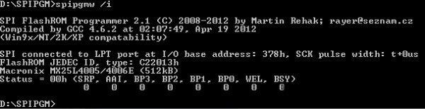
The current version of SPIpgm 2.1 supports the entire desktop family of Windows, Linux, and DOS. I very much doubted that everything would work on Win7 / Vista, LPT programmers for this OS are very fastidious. Nevertheless, everything coincided with the statement of the developer. do not forget that UAC must be disabled (I have it disabled by default). Turn off the PC completely, connect the programmer, turn it on and use command line. Using the cd operator, we go to the desired directory where the programmer is located. Because we are in a Windows environment, we need to use spipgmw, spipgm is used in DOS and Win9x, however spipgmw can also be used in Win9x. The screenshot below shows that there are no problems, the programmer and software work fine in a modern environment, which is extremely rare in such tasks
However, I note that I sewed in DOS, it’s more familiar to me) The simpler the OS, the more reliable it is. But I don’t agitate to switch to it completely) It's just more interesting for me to use DOS for such things. From experience with other self-made programmers, I can say that in WinXP this programmer will no doubt work
If the programmer cannot recognize the microcircuit (see the screen below), then it is either dead, or the programmer is not assembled correctly or power is not supplied, there is no mass. The second option is more likely
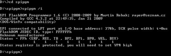
This is what the command line will answer if the programmer is not built correctly. The chip is not recognized, i.e. failure
Mutim DOS or "I'm not looking for easy ways"
DOS isn’t so difficult for yourself. You can make a bootable floppy disk using the Windows OS itself through formatting the floppy disk and put the folder with the programmer and new firmware there, after loading (on the working PC) into the console, use the programmer
The second option is to make DOS on disk or use the ready-made DOS 6.22 image. But the programmer itself will need to be written to a separate flash drive, because if we remove the dump, it won’t be able to write to the disk, although if reading is not required, you can roll it directly to the disk with the DOS
The third option is to create bootable flash drive, This is the most convenient and modern option for today. A good method is described, for example, here
I can still recommend using the MultiBoot project - a multi-boot flash drive. In the end, we get a very functional tool for all occasions, a powerful such resuscitator. DOS is also there with support for NTFS, long names, and more. Instructions for creating there, everything is very convenient and legal
We assume that we launched DOS (Linux owners do not need this, they have a SPIPGM file without extension) We go to the command line, go to the programmer folder. To find out the basic commands, we simply run spipgm
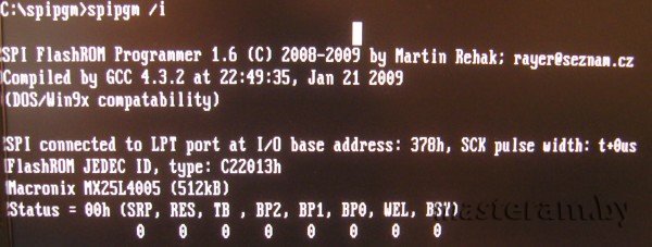
In DOS, everything was also recognized without any problems.
The main programs that we will need:
spipgm / i - chip identification in the programmer. If the programmer is made and connected correctly, then the microcircuit (if it is in the list above) is recognized and, accordingly, it will be possible to work further with it
spipgm / d dump.rom - read the contents of the chip into the dump.rom file
spipgm / e - complete erasure of the contents of the chip, it is recommended to do before recording
spipgm / p new.rom - firmware, writing to the microchip data from the file new.rom - the whole and correct firmware file for a specific motherboard, you can take it from the manufacturer’s website or remove it from another microcircuit of a similar board
spipgm / u - unlock, i.e. unlocking the chip for recording, if there is such protection
In total, in order to accomplish what we had planned for recovery, we need to execute a sequence of commands:
1. spipgm / i - identify
2. spipgm / u - unlock
3. spipgm / e - erase the chip with curved content
4. spipgm / p new.rom - flashing the correct firmware
I draw attention to the fact that if we do everything in the Windows environment, then instead of spipgm we use the spipgmw command
After that, we cut down the PC through the shutdown button and turn off the programmer
Attention! All manipulations with the LPT port must be done only with the board powered off. Those. Before connecting or disconnecting anything from LPT, it is necessary to completely turn off the power supply, put the power supply switch in the Off position (or remove the cable), wait 10 seconds (capacitors are discharged), and only then connect or disconnect something. If you do not follow this simple rule, then there is a great chance to remain without LPT, he is very moody to such things because of his insecurity
Afterword
Total, now my board has been restored and received a second life. I will use it as a test and service training ground to test another kit. My readers will now also be able to revive something that has been lying around for a long time and waiting in the wings
Also pay attention that this method Suitable for recovery not only on motherboards, but also on video cards, both ATI / AMD and nVidia. Many of the microcircuits that are indicated above in the compatibility list are also installed on video cards, only they are always soldered to the video card, therefore, to restore the video, you will need the ability to solder SMD. There are usually 2 options here - soldering mikruha and installing it on a pre-etched pad of the programmer or soldering wires to the video adapter board itself
I hope my experience will help someone save money and hardware, because it will not be wise to apply for such services in the SC - such a fee on the secondary market is just comparable to the cost of repair, and therefore you need to either restore it yourself or go to the store for a new one. If I have the opportunity to pick the programmer and "s with chips 20 pin (in square beds are), then the material will be supplemented. Thank you for your attention.